WFDD
Wireless Flip-dot Display
For those not familiar with the working principle of flip-dot displays, try this article or blog.
I recently acquired some flip-dot displays, planning to use them as information panels in TAKT. Fortunately, the pinouts for these displays were already reverse-engineered, making my task easier. I mostly focused on writing drivers for the specific driver boards. This involved modifying the original driving PCBs, detaching the MCU from the driving circuitry, and replacing it with an ESP32.
Typically, in transportation vehicles, these displays connect to the IBIS bus, a low-speed UART@1200b with 24V logic levels. (Other displays may provide connectivity via RS232, RS485, or Ethernet).
A master controller loads these displays with information like line number, final stop, next stop, and so on. The display then cycles them automatically.
Initially, I attempted interfacing with the display via IBIS for which I was able to get specifications (here).
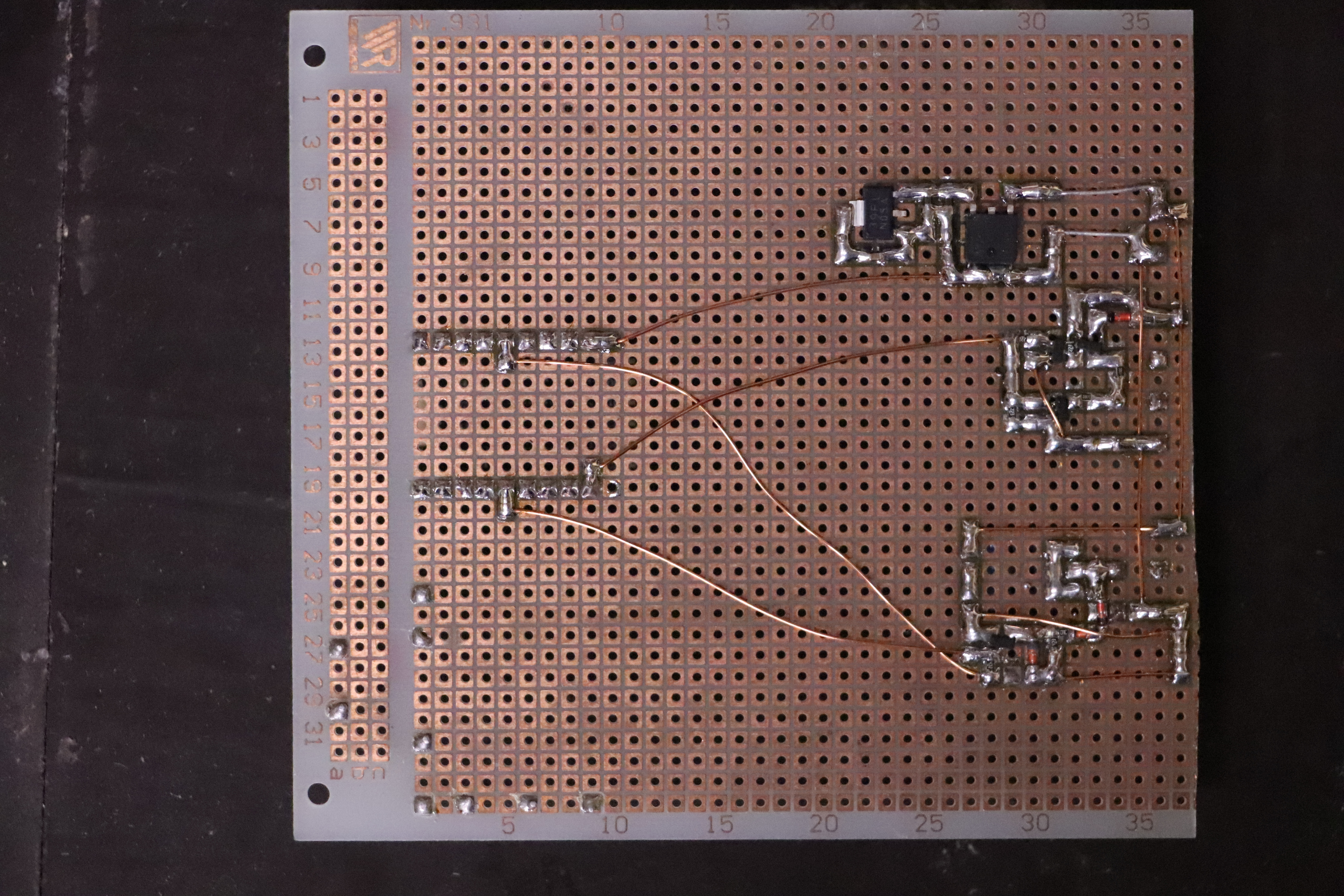
I used a simple UART to IBIS interface, built to specification.
That doesn't work at all.
The original driver is intended for use as a transportation info panel, this use case is however far from what I consider usable or fun, not to mention low data rates.
So, the next step was to use ESP32 to drive the display directly, providing more flexibility and control.
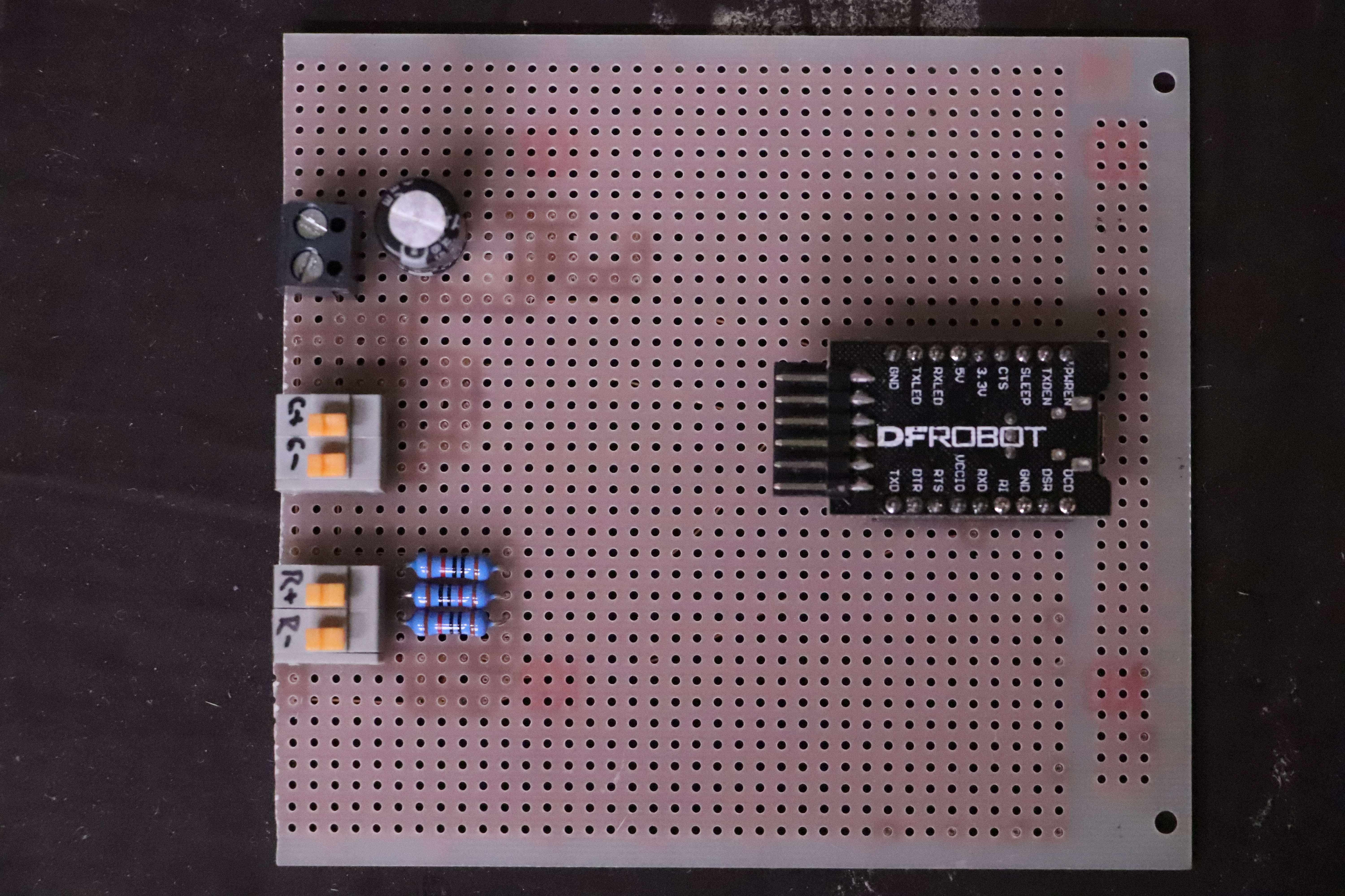
Custom UART to IBIS interface
General Flip-dot Driver Board Overview
From my analysis of available HW, it seems different manufacturers have a similar design approach for addressing and driving circuitry. A typical driver board will have:
- Cascaded 74HC283 3 to 8 demuxes for addressing
- Sink and source transistor arrays
- A current source optimized for pulsed operation
- Additional components like MCU, EEPROM, LDO…
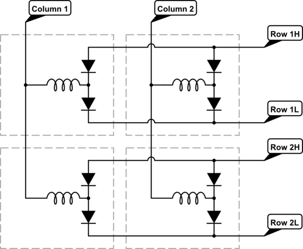
These displays usually comprise a row driver board with an MCU, connected in parallel to all modules. Column drivers are present on each module's PCB. The 3 to 8 demuxes are arranged to select a sink or source transistor on one of the rows/columns, controlling the desired pixel coil.
Pixel flipping and flopping require a change of coil current polarity, that's why a sink and source transistors are connected to both sides of the pixel coil. Coil separation is done with two diodes for each coil, that way coils can be multiplexed.
Coil connection
Example usage of demuxes

LAWO Display:
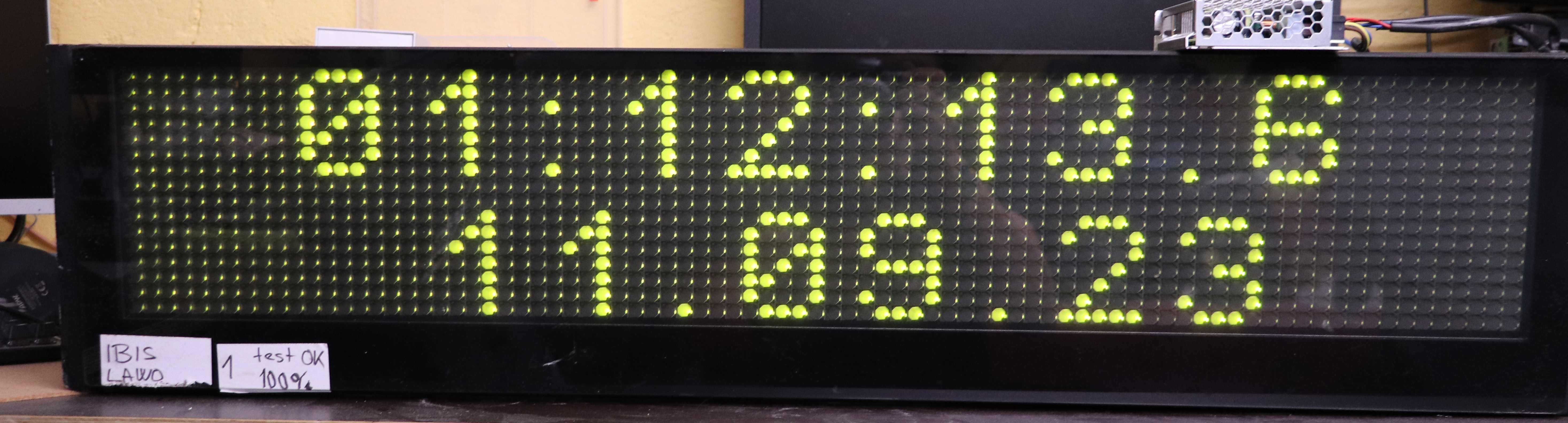
This display consists of three 28x16 modules, totaling an 84x16 resolution. Each pixel has a green LED, consuming totaly ~1.1A@24V. The column driver used is the FP2800A.
Modifications:
LAWO MCU & row driver with ESP32 driverboard
To drive this display, I disconnected the transistor arrays from their multiplexers and attached them to shift registers controlled by the ESP32.
The address and control signals for modules were connected to a couple of Schmitt triggers used as level shifters.
The display's pinout and other details are available in this repository. For driving the FP2800A, I used this library.
BUSE Displays:
Largest of the BUSE displays
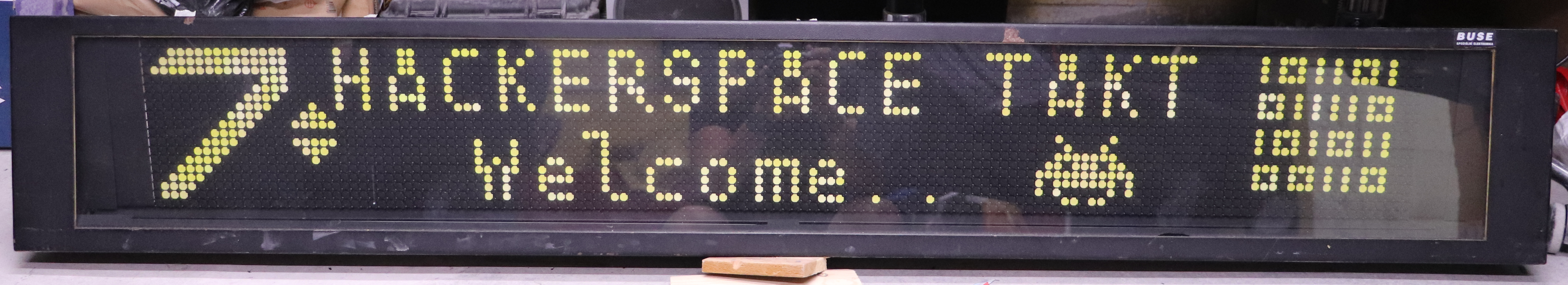
Similar to LAWO, these displays are module-based. I have three displays with resolutions: 140x19, 112x19, and 28x19. The row and column driver implementations are comparable to LAWO, but with discrete column drivers. The module pinouts are accessible here (DE) and here (CZ) (page 16).
Modifications:
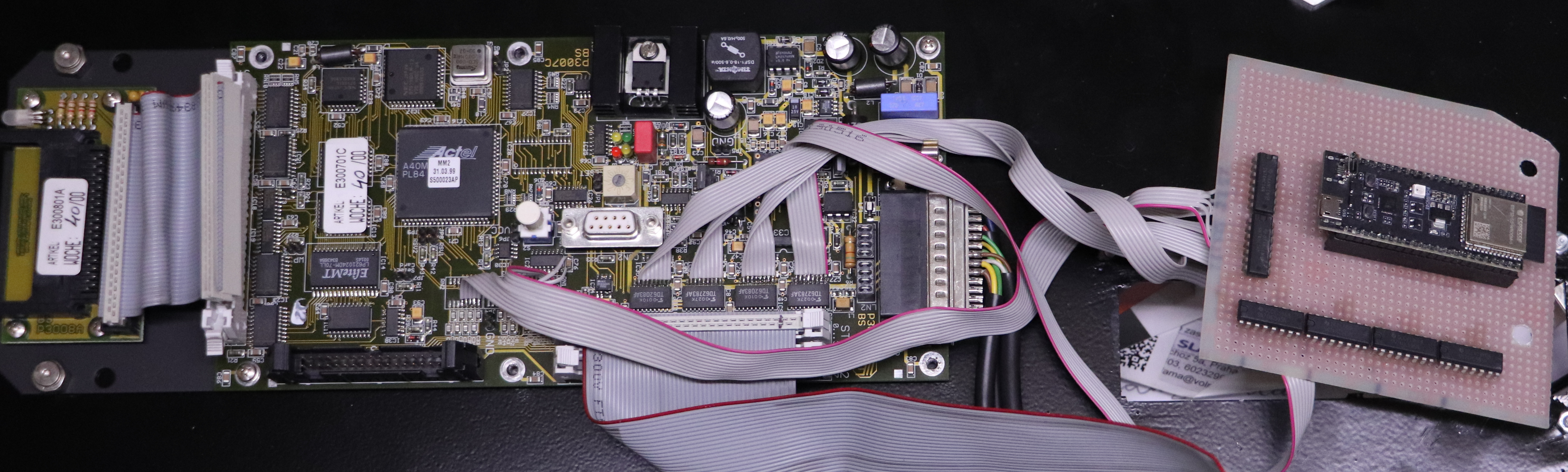
BUSE MCU & row driver board
With ESP32 connected
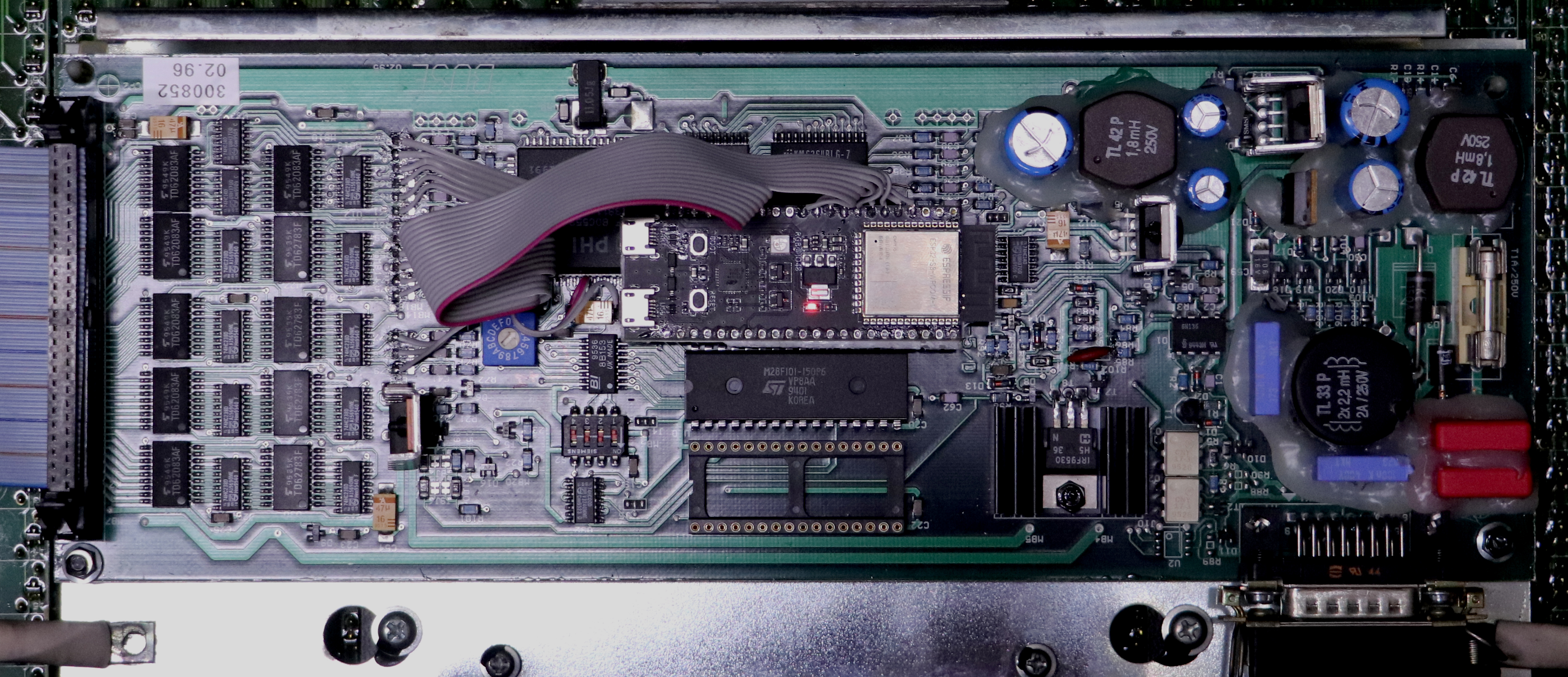
Using the resources mentioned, I traced various address and enable pins and disconnected the onboard MCU, replacing it with the ESP32. Notably, the address signals for the modules use 12V logic levels for better signal integrity. A resistive divider on each module PCB converts the 12V logic back to 5V TTL.
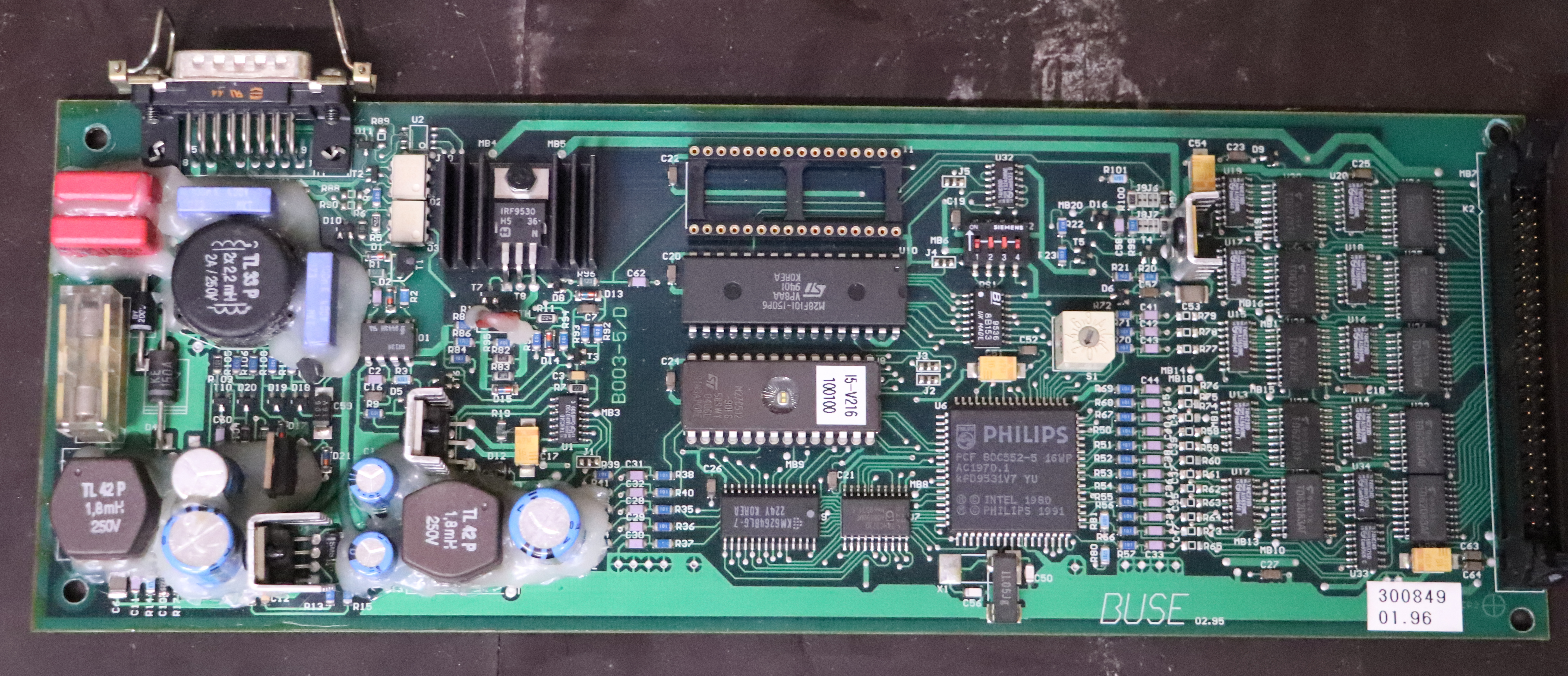
BUSE driver board signals:
For driving BUSE displays with another MCU, we need to connect 15 different signals. The table below shows which components are removed for wiring in our MCU of choice. This is for the BUSE driver board labeled B003-5/D. 5V power can be obtained by connecting to some of the blocking capacitors, that are near logic ICs.
| Component: | Signal: |
|---|---|
| R79 | Row address bit0 |
| R78 | Row address bit1 |
| R77 | Row address bit2 |
| R76 | Row address bit3 |
| R75 | Row address bit4 |
| R74 | Write/Erase pixel |
| R58 | Column address bit3 |
| R59 | Column address bit4 |
| R60 | Column address bit0 |
| R61 | Column address bit1 |
| R62 | Column address bit2 |
| R63 | Module address bit0 |
| R64 | Module address bit1 |
| R73 | Write pulse |
| R65 | Module address bit2 |
Software:
After finishing hardware modifications, I wrote the driver libraries, available in this repository. The ESP32 firmware source is here.
During development, I found a helpful project on Github. It laid the groundwork for my ESP32 firmware, meaning I only needed to focus mostly on display drivers.
Display Performance:
FPS: Flips per second
Due to individual pixel control, there's a limit to how frequently a display can refresh. Dot flipping requires magnetizing its core, with too short a pulse causing incomplete flips. To enhance performance, I'm considering hardware modifications for the LAWO display, potentially doubling its speed.
Currently, I achieved 4FPS with LAWO and 1.2FPS with the largest BUSE.
Future Development:
Soon™
Tetris-> DONEGame of life-> DONE- The Dinosaur Game
Snake-> DONEBluetooth gamepad->PS2 Wireless gamepad -> DONE (Sort of)- Web interface
Music-visualizer-> DONE- UV illumination
- Last DHCP lease IP
Resource Links:
- Display driver libs
- ESP32 FW for this project
- Base ESP32 FW
- BUSE module pinout
- LAWO module pinout
- FP2800A Arduino library
- Flip-Dot as core memory
🄯trimen 2023